Inside an Electric car and how it works
Electric powered cars are becoming popular in the present time because of the ever-increasing fuel problems as well as the environmental crisis. In fact, there are about 250,000 electric hybrid vehicles being sold every year since 2007.


Electric powered cars are becoming popular in the present time because of the ever-increasing fuel problems as well as the environmental crisis. In fact, there are about 250,000 electric hybrid vehicles being sold every year since 2007. With this, electric charging stations are now found in most countries.
Electric cars are known to be very efficient and they consume less energy making them environmentally friendly automobiles. But have you ever wondered what the components of an electric powered car’s engine are, and how they work?
Electric cars function by plugging into a charge point and taking electricity from the grid. They store the electricity in rechargeable batteries that power an electric motor, which turns the wheels. Electric cars accelerate faster than vehicles with traditional fuel engines – so they feel lighter to drive
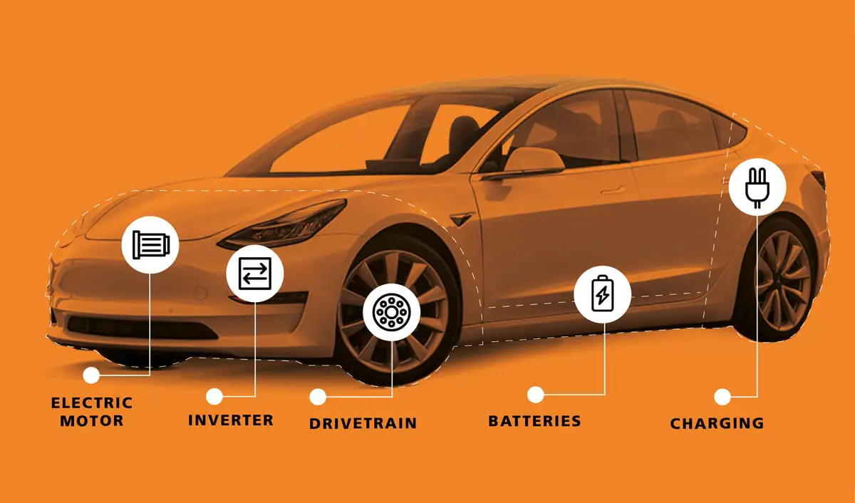
The heart of an electric car is the combination of:
- The electric motor
- The motor's controller
- The batteries
Battery
The battery of an electric car can be charged through the use of ordinary grid electricity at a specialized power station. But aside from the conventional lithium-ion battery technologies, there are also other major battery technologies which can be used for electric cars.
- Lithium-Ion Batteries: This battery technology gives extra performance and range. However, it also carries the highest price tag. Lithium-ion batteries are lighter than Lead acid and Nickel metal. These are also the batteries used in digital cameras and smartphones.
- Lead Acid Batteries: This battery technology is the most popular. It is also the cheapest among the battery technologies. What’s good about it is it’s 97% recyclable.
- Nickel Metal Hydride Batteries: This battery technology provides higher output and better performance but it costs much more than lead-acid batteries.
Motor Controller
The motor controller of an electric car administers its complete operation and the distribution of its power at any given moment. It acts as a floodgate between the motor and batteries. It helps monitor and regulates all key performance indications such as the vehicle’s operator, motor, battery, and accelerator pedal. It has a microprocessor which can limit or redirect current. It is used to either improve the mechanical performance of the car or suit the operator’s driving style. There are also more refined controllers which are capable of greater accuracy and thus, higher efficiency.
Electric Engine
Unlike a gasoline engine with lots of moving parts, an electric engine or motor only has one moving part. This makes it a very reliable source of motive power. Choosing an electric engine depends on your car’s system voltage. They can be structured to use either AC or DC current. AC motors are less expensive and lighter compared to DC engines. They are also more common and they tend to suffer from less mechanical wear and tear. However, AC technology requires a more refined or sophisticated motor controller.
Here is an in depth of how the major components of electric car functions:
The controller takes power from the batteries and delivers it to the motor. The accelerator pedal hooks to a pair of potentiometers (variable resistors), and these potentiometers provide the signal that tells the controller how much power it is supposed to deliver. The controller can deliver zero power (when the car is stopped), full power (when the driver floors the accelerator pedal), or any power level in between.
The controller takes in 300 volts DC from the battery pack. It converts it into a maximum of 240 volts AC, three-phase, to send to the motor. It does this using very large transistors that rapidly turn the batteries' voltage on and off to create a sine wave.
When you push on the gas pedal, a cable from the pedal connects to these two potentiometers: The potentiometers hooks the gas pedal and sends signal to the controller.
The signal from the potentiometers tells the controller how much power to deliver to the electric car's motor. There are two potentiometers for safety's sake. The controller reads both potentiometers and makes sure that their signals are equal. If they are not, then the controller does not operate. This arrangement guards against a situation where a potentiometer fails in the full-on position.
The controller's job in a DC electric car is easy to understand. Let's assume that the battery pack contains 12 12-volt batteries, wired in series to create 144 volts. The controller takes in 144 volts DC, and delivers it to the motor in a controlled way.
The very simplest DC controller would be a big on/off switch wired to the accelerator pedal. When you push the pedal, it would turn the switch on, and when you take your foot off the pedal, it would turn it off. As the driver, you would have to push and release the accelerator to pulse the motor on and off to maintain a given speed.
Obviously, that sort of on/off approach would work but it would be a pain to drive, so the controller does the pulsing for you. The controller reads the setting of the accelerator pedal from the potentiometers and regulates the power accordingly. Let's say that you have the accelerator pushed halfway down. The controller reads that setting from the potentiometer and rapidly switches the power to the motor on and off so that it is on half the time and off half the time. If you have the accelerator pedal 25 percent of the way down, the controller pulses the power so it is on 25 percent of the time and off 75 percent of the time.
Most controllers pulse the power more than 15,000 times per second, in order to keep the pulsation outside the range of human hearing. The pulsed current causes the motor housing to vibrate at that frequency, so by pulsing at more than 15,000 cycles per second, the controller and motor are silent to human ears.
In an AC controller, the job is a little more complicated, but it is the same idea. The controller creates three pseudo-sine waves. It does this by taking the DC voltage from the batteries and pulsing it on and off. In an AC controller, there is the additional need to reverse the polarity of the voltage 60 times a second. Therefore, you actually need six sets of transistors in an AC controller, while you need only one set in a DC controller. In the AC controller, for each phase you need one set of transistors to pulse the voltage and another set to reverse the polarity. You replicate that three times for the three phases -- six total sets of transistors.
Most DC controllers used in electric cars come from the electric forklift industry. The Hughes AC controller seen in the photo above is the same sort of AC controller used in the GM/Saturn EV-1 electric vehicle. It can deliver a maximum of 50,000 watts to the motor.
How it works
A simple DC controller connected to the batteries and the DC motor. If the driver floors the accelerator pedal, the controller delivers the full 96 volts from the batteries to the motor. If the driver take his/her foot off the accelerator, the controller delivers zero volts to the motor. For any setting in between, the controller "chops" the 96 volts thousands of times per second to create an average voltage somewhere between 0 and 96 volts.
Heavy cables (on the left) connect the battery pack to the controller. In the middle is a very large on/off switch. The bundle of small wires on the right carries signals from thermometers located between the batteries, as well as power for fans that keep the batteries cool and ventilated.
The heavy wires entering and leaving the controller. An AC controller hooks to an AC motor. Using six sets of power transistors, the controller takes in 300 volts DC and produces 240 volts AC, 3-phase. See How the Power Grid Works for a discussion of 3-phase power. The controller additionally provides a charging system for the batteries, and a DC-to-DC converter to recharge the 12-volt accessory battery.
Source: How stuff works, Did you know cars